US $82.49
Original Price : US $95.92 (14%)
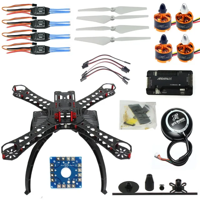
Limited Price DIY RC Drone Quadrocopter X4M380L Frame Kit APM 2.8 Flight Control GPS F14893-K with Free Shipping Worldwide!
 4.78
4.78Related Products :
RC Drone Quadrocopter 4-axle Aircraft Kit 500mm Multi-Rotor Frame 6M GPS APM2.8 Flight Control Flysky FS-i6 Transmitter F08151-M
M4 M5 M6 Hand Tighten Screw Aluminum Alloy Handle Adjustable Screws DSLR Camera Photography Accessories
XILETU XJ-8 Tripod phone tripod mount Head Bracket Mobile Phone Holder Clip For Phone Flashlight Microphone With Spirit level
JEYI VolleyStar-PRO Black Heat Sink Heatsink M.2 NVMe SSD NGFF TO PCIE X4 Adapter MKey Port Card PCI-E 3.0 x4 Full Speed RGB LED
Product description
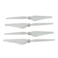
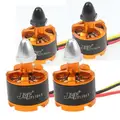
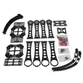
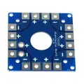
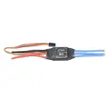
[32627788853]DIY RC Drone Quadrocopter X4M380L Frame Kit with APM 2.8 flight control Motor ESC Props Unassembled,buyer need to assemble by themselves. Package include: X4M380L Fiberglass Frame *1 Clockwise Brushless Motor *2 Counter-clockwise Brushless Motor *2 30A Brushless ESC Speed Controller *4 9443 Propeller *2 KK Connection Board *1 APM2.8 Flight Control *1 6M GPS with Compass *1 3.5mm Bullet Connector *12 20cm Hook and & Loop Fastening Tape *1 T Plug Male Connector Silicone Wire *1 5pcs 10cm Servo Receiver Extension Lead Wire Cable*1 GPS Folding Antenna Mount Holder*1 Before you can configure your APM, you will need to first connect everything together. This guide will show you all the cables and parts that you will need to connect to your APM. Typical Quadcopter Layout Please note the illustration Below highlights a (TYPICAL) installation. It contains optional equipment including a Camera Gimbal and a Battery Monitor and it utilizes an ESC wired "Y" power connection rather than the power distribution board common to many MultiCopters. 1. Connecting your motors and RC gear Overview of connections on the Ardupilot Mega v2 board Note: the instructions below are for regular RC receivers with PWM output (one cable per channel). If you're using a "PPM" receiver (one cable carries all channels), follow the instructions . Before you can configure your Arducopter, you will need to first connecteverythingtogether. This is quite easy. You need to connect your RC receiver to the Input side of the board. You can use the cables included with your Arducopter Kit, or if you are using another frame, you can use jumper cables, or female to female servo cables Connections between RC receiver and Ardupilot Mega v2 board If you are using female to female servo cables, the ground (black) side of each connector must be on the outside for the board, the signal (white/orange) needs to be on the inside as shown below. Connecting with straight connectors Connecting with right angle connectors If you are using a multi-pin connectorthat was included with your Arducopter Kit, connect them as shown below Input Side for RC reciever Output side to PDB Please note, that your ESC, connectors should be plugged in the the output side, it is suggested that you only use power from one of your ESC's. This can be dune by cutting the red wire on all but one of the ESC's, or by using a special adaptor. 2. Connecting ArduCopter motors Once again if you are using an Arducopter Kit, with the PDB, then you dont need to worry about this if you soldered everything correctly as the motors are assigned to the correct pins with the cables you plugged connected in the previous step. However you will neet to make sure your motors are spinning in the correct direction. The images below show the possible arducopter configurations with correct motor orientation Quick Tip: If your motor is not spinning in the correct direction, simply switch the position of any two of the ESC-motor wires. Arducopter Quad Arducopter Tri Arducopter Hexa, Octa, and Y6 Arducopter OCTA QUAD (X8) Connecting a Roll-Tilt Camera mount 3. Connecting Optional Sensors Sonar - Ultrasonic Rangefinder AC2 supports the MaxSonar line of sonars for low level altitude hold and in the future collision avoidance. Below 10 meters sonar is primarily used for altitude hold. Above 10 meters, the barometric sensor is used. GPS is not required for altitude hold. Connect your Ultrasonic Sensor to the A0 port of your Ardupilot Mega v2 board The sonar sensors are quite sensitive to noise, adding something like a ferrite choketo your cable could help. The most important is to mount your sonar away from other electronics like ESC, or wireless telemetry modules. Possible Causes of sonar Interferance Electrical noise caused by ESCs, Servos, or switching BEC's on the same circuit as the Sonar EMF radiation from motors, motor wires, ESC's or Xbee. Acousticnoise from propellers Vibration from motors, props, etc. Optical Flow Sensor The optical flow sensor is used to improve thepositionhold accuracy of your arducopter. This sensor is supported from Arducopter 2.6 and above. Connecting the optical flow sensor to APMv2 Power, GND, NCS pins should be attached to A3 MISO, MOSI and SCLK pins should be directly soldered to the pins shown above Default mounting is lens pointing down, pins forward Its a good idea to secure the wires with some cable ties so they dont break off over time
Important Informaiton to Every Value Clients:
For theSelling Peak Season, someLogistic may delay for some days.especiallye-packet to Russion,Most Western European Countries,and all shipping to Brazil .if you don't receive the parcels on time ,pls help us wait some more days.Pls contact us freelyif you have any questions rather thanmake claimor leave negative feedback without contact.Aliexpress Approved Shipment--China Post Ordinary Small Packet Plusin Selling Peak Season,We guarantee 45 days delivery to main countries ;55 days to Russia; 90 days to Brazil!


